ArC2Control User’s Guide
ArC TWO is our next generation electronic characterisation tool which enables massive parallel testing of devices with arbitrary interconnections. It can achieve sub-100 ns pulsing across 20 V of voltage.
This guide will cover installation, firmware management and basic usage of the ArC TWO graphical interface. It is mainly intended for end-users but there’s separate developer’s guide if you want to start building upon the ArC TWO GUI platform.
This guide does not cover general information, hardware or protocol documentation on the ArC TWO itself. Please see our introductory User’s Guide for that.
Minimum system requirements
ArC TWO requires a Windows 10/11 or Linux computer with at least 4 GB of RAM (8 GB or more recommended). A USB-3.0 port is also required to allow ArC TWO to operate at full speed. Please note that on Linux the minimum glibc supported by ArC TWO is 2.14. This essentially means every distribution newer than CentOS 7. Additionally libusb-1.0 is required which should be available on most distributions released after 2015. Linux systems based on musl libc (for instance Alpine Linux) are not supported.
Getting started
Installation of the CESYS USB Drivers
ArC TWO is an FPGA-based tool and uses a Xilinix FPGA implementation provided by CESYS GmbH: the EFM-03. In order for ArC TWO to operate you need to install the CESYS USB Drivers for your operating system. On Windows you need to install the udk3usb drivers from the CESYS beastlink distribution (beastlink-1.0-windows-free → driver → udk3usb-drivers-windows-1.3.exe). On Linux scripts that generate packages for your distribution are available from our github.
Installing the ArC TWO Control Panel
ArC TWO Control Panel (ArC2Control) is a handy application that is oriented towards crosspoint operations. That means that the ArC TWO channels are organised in a 32 by 32 fashion essentially creating 32 different crosspoints. In a crossbar configuration this allows for up to 1024 interconnection points. This is by no means indicative of the full capabilities of ArC TWO but it’s a common enough scenario to have its own standalone application.
Since ArC2Control is still in active development the installation requires the presence of a 64-bit Python interpreter. Please note that 32-bit interpreters will not work. Python versions > 3.8 are routinely tested and they should be expected to work. On Windows we strongly recommend you install the official Python distribution instead of alternative distributions such as Anaconda. On Linux you can use the Python interpreter that comes with your distribution. Once Python is installed and available you can install ArC2Control with the following command in a command line interpreter (any Linux shell or Windows CMD or Powershell).
python -m pip install arc2control
Or, alternatively, for the latest development snapshot (requires git to be available)
python -m pip install git+https://github.com/arc-instruments/arc2control
Please note that on Linux it is strongly recommended that you install ArC2Control as a regular user, not root. Regardless of your installation method you can launch ArC2Control with the following command
python -m arc2control
On stable releases Windows installers and Linux AppImages will be made available from the release page.
The ArC2Control Interface
Overview
ArC2Control is our recommended way to familiarise yourself with the ArC TWO platform. It is divided into different functional panels.

The different functional areas of ArC2Control
These are the following functional areas of ArC2Control:
Main Toolbar: contains buttons that deal with dataset handling as well as firmware management.
Device History: lists all experiments performed on devices defined by crosspoints, oldest first. Depending on the experiment you can double click on any experimental entry to bring up the collected data and experimental attributes.
Data Plot Panel: displays all biasing history for the selected crosspoint
Connectivity Panel: controls connection to ArC TWO, firmware selection and channel mapping management.
Manual operations: handles manual biasing or reading actions performed to selected crosspoints.
Crossbar view: Current resistance values of all devices in the crossbar.
Module panel: Experiment panel management. Both built-in and external modules are available here.
Display and plotting options: manages type of value to display (resistance, conductance, current), y-axis scale and number of historic data points to display.
Starting a new session
When you first start ArC2Control you will be greeted with crossbar configuration dialog which allows you to configure the size of the crossbar that will be managed by ArC TWO.
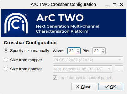
The crossbar configuration dialog
You can specify the size of the crossbar either manually, through a mapping scheme or by loading an already existing dataset. In the latter case you can additionally load the dataset in ArC2Control so that you can continue working on it.
Connecting to ArC TWO and firmware management
Before connecting to ArC TWO you will need to install the firmware required by the on-board FPGA. If no firmware is found, ArC2Control will prompt you to open the firmware manager. You can also bring up the firmware manager by clicking the corresponding button on the main toolbar.
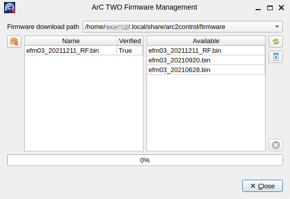
The firmware management dialog - Firmware file efm03_20211211_RF.bin is already downloaded.
Clicking the Refresh available firmwares button (top right) will query the
ArC Instruments Server for available firmwares. It will then list all available
firmwares (newest first) on the right-hand panel. You can download the firmware
by clicking the Download selected firmware button which should then appear on
the locally installed firmwares on the left-hand panel. New firmwares will be
posted occasionally so check the firmware manager for updates. There are
several locations that ArC2Control can store firmware (see Firmware download
path). It is recommended that you use the user-local directory which is
%APPDATA%/arc2control/firmwares on Windows or
~/.local/share/arc2control/firmwares on Linux. Using a global directory
would allow you to share the firmware files among multiple users of the same
computer but in that case you need to start ArC2Control with elevated
permissions which is generally not recommended.
Closing the firmware manager will update the available firmwares available in the Connectivity Panel on the main ArC2Control UI. If you have already plugged in and powered-on an ArC TWO board the board ID will be available next to Connect/Disconnect ArC2 button. If not, connect and power-on an ArC TWO board and press the Refresh button which should be populated with all discovered device IDs. Make sure you select the firmware you downloaded (or any other) so that it can be loaded on the instrument. Newest firmwares are listed higher on the list. Upon successful connection the green Connected indicator will lit up and you are now ready to use ArC TWO. Clicking the Connect/Disconnect ArC2 button will disconnect the tool and the red Disconnected indicator will now appear.
Control modes and idle status
ArC TWO provides two control modes of operation, found under the ArC2 Connection panel. In Internal mode ArC TWO biasing will be diverted to the internal switching matrix. In Header mode it will use the external control scheme. In the context of the 32NNA68 daughterboard, for example, that means either the PLCC68 socket (internal) or the header bank (header). Different daughterboard utilise the control modes differently so follow the documentation provided with the daughterboard.
The Idle Status control determines how ArC TWO will manage the channels once an operation has been completed. In all cases voltage will be set to 0.0 V but channel connections will differ depending on the selected option. There are three different possibilities: (a) Float to completely disconnect the channels from biasing; (b) Soft GND will set all channels to 0.0 V but still connect them to output source and (c) GND will switch the channels to the physical ground.
The channel mapper
ArC TWO presents 64 arbitrarily interconnected channels. In order to effectively utilise them for a specific experimental scenario a channel mapper is required. The channel mapping mechanism provides a way to map the internal ArC TWO channels to useful word- and bitlines in a crossbar configuration. ArC2Control comes with a set of default mappers, namely PLCC 32×32 that can be used for packaged devices; Test board for debugging purposes; 64-pin probecard for our standard 1R probecards; SA 64-pin probecard for our standard 1R probecards in stand-alone configuration (1 device per wordline) and BNC breakout for the 6×6 BNC board. Channel mappers can be selected on the fly from the Channel mapping dropbown located under the ArC2 Connection panel.
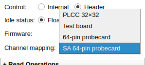
The channel mapper dropdown listing mappings suitable for a 32×32 crossbar array.
Note
The mappers available on the Channel mapping dropdown are only the ones suitable for the currently configured crossbar size. For instance if you setup a 32×32 crossbar the BNC breakout channel mapping will not be available as it is only applicable 6×6 crossbar configuration. You can configure the crossbar dimensions during ArC2Control startup.
You can create additional mappings depending on your experimental setup. Further documentation on how to do so can be found in our developer documentation.
The crossbar view
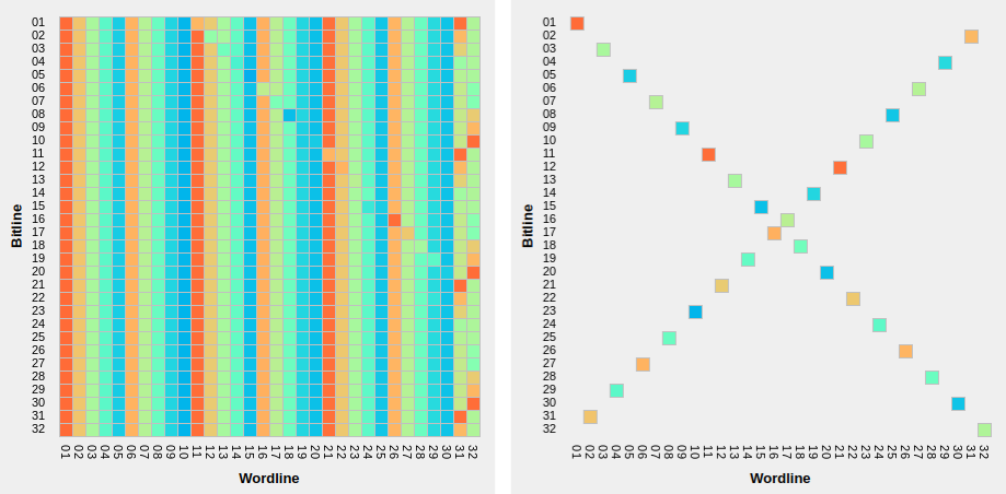
A fully populated 1 kb 32×32 crossbar (left) and a crossbar with one crosspoint per wordline (“standalone array”)
The crossbar panel shows an overview of the current status of all configured crosspoints. Depending on the active mapper and crossbar configuration during ArC2Control startup the number of crosspoints as well as the geometry of the array itself can vary. On the image above the crossbar on the left depicts a full 32×32 array whereas the one on the right a “standalone array” ie. an array with only one crosspoint per word-/bitline. Hovering over a crosspoint will display the coordinates and value of the crosspoint under the cursor. Double-clicking on the crossbar view will select the crosspoint under the cursor. You can hold down the Ctrl key and double-click on additional crosspoints to expand the selection. Alternatively you can click and drag on the crossbar view to select more than one crosspoints. The current selection can be cleared by right-clicking.
Device history
The Device History panel lists all experiments performed to individual crosspoints in chronological order (oldest first). Depending on the experiment, double-clicking on an experiment will bring up the collected data and the experiment attributes, if any.
Additionally, right clicking on a crosspoint ID will allow you to export
the biasing history of that crosspoint which includes manual operations
as well as experiments performed. You can export the full history or a
specific range in a csv file.
Manual operations
ArC2Control offers a series of manual operations that can be applied to one or more crosspoints. You can select the read-out voltage used throughout the software and you can read one or more selected crosspoints. ArC2Control will optimise the biasing scheme depending on the number of selected channels. If channels are located along the same bitline one parallel read instruction will be issued with current sinked on the bitline. If channels are located in more than one bitlines parallel reads will be done for each one of the selected bitlines. When reading the whole array with Read All a series of parallel reads will be done for each of the bitlines in the current configuration.
Note
Although read-out voltage is configured globally modules can still use a different read-out voltage depending on their functionality. Most of the built-in modules will offer you an option to configure read voltage without affecting the global read-out voltage.
The same philosophy applies to manual pulse and pulseread operations. The positive and negative polarities can be configured independently or the two can be locked to the same amplitude and pulse width by toggling the Lock checkbox. When pulsing you have the option of applying a singular pulse or pulsing and then immediately reading the selected crosspoints.
Pulse and reads are denoted with separate symbols on the data plot panel. For operations that do not return a value (pulse only) no value is plotted on the top half of the data plot but the pulse properties are still recorded.
Display options
The final panel of the main ArC2Control UI is the Display Options panel which controls the value displayed on the main data plot as well as the scaling of the X and Y axes. You can select between resistance, conductance, current or absolute current. You can also control the number of displayed points, although it is recommended that you keep the value relatively low for data intensive operations.